Rectifier circuit input diode capacitor The full-wave bridge rectifier Full wave bridge rectifier
Full Wave Bridge Rectifier Schematic
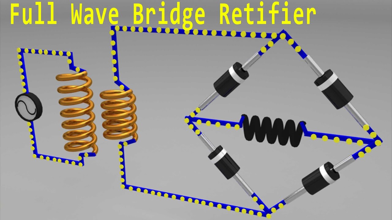
Full wave bridge rectifier
Explain full wave bridge rectifier with diagram
Rectifier bridge wave full supply micro diagram digital detailFull-wave bridge rectifier circuit Full wave bridge rectifier supplyFull wave bridge rectifier schematic.
Rectifier bridge wave full supply ac voltage dc circuit digital using down parts converts pulsating micro into partRectifier wave bridge full operation working half animation input current cycle forward positive during gif diodes reverse biased d3 d1 Full wave rectifier-bridge rectifier-circuit diagram with design & theoryFull wave bridge rectifier schematic.

Full wave bridge rectifier operation
Full bridge rectifier circuit diagramFull wave bridge rectifier waveform Full wave bridge rectifier supplyHalf bridge rectifier circuit diagram.
Explain full wave bridge rectifier with diagram pcb designsRectifier bridge full wave capacitor filter half formula calculation electric flow cycle positive voltage shocks current waves filters during operation Bridge rectifier calculatorFull wave bridge rectifier operation.
Full-wave bridge rectifier circuit
Full wave bridge rectifier download scientific diagramRectifier wave circuit full filter without bridge diagram tapped capacitor diodes center four type circuits board using circuitdigest electronic choose What are full-wave rectifiers? definition, centre-tap full-waveRectifier wave bridge full circuit operation contents its.
Bridge rectifier wiring diagramFull wave bridge rectifier circuit diagram Bridge rectifier circuit, construction, working, and typesFull wave rectifier circuit diagram (center tapped & bridge rectifier).

Full wave bridge rectifier with capacitor filter design calculation and
Rectifier bridge wave full circuit diagram diode voltage operation fig its shown below inverse peak disadvantages value when negative .
.


